Monitoring Solar Power
With the lights set up and working, next I wanted to add monitoring of different systems in the van. The first one was monitoring solar power by interfacing with my charge controller.
What you’ll need
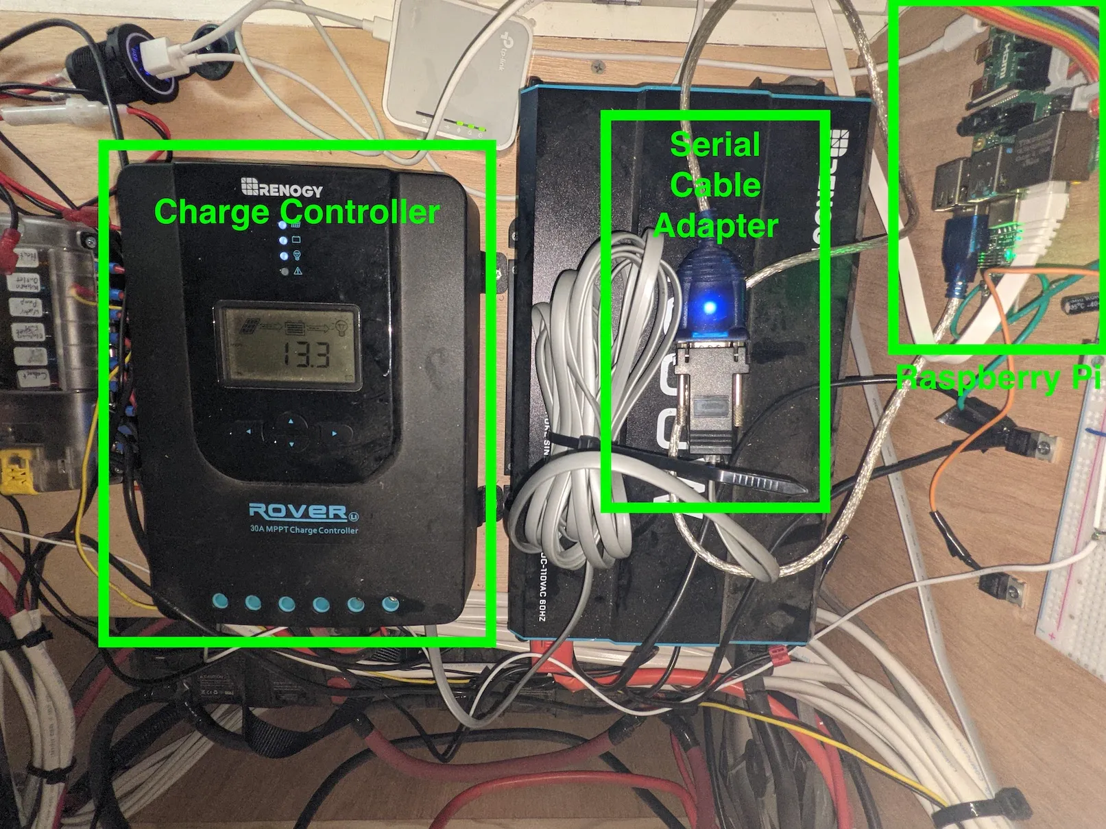
Section titled “What you’ll need”- Renogy Rover Charge Controller — I have the 30A version. This setup should work with any charge controller in the Rover series.
- USB Serial Dongle — For serial communication from the Raspberry Pi to the charge controller.
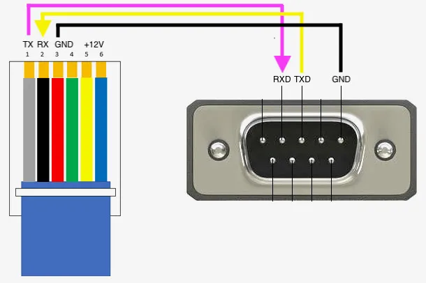
- DB9 to RJ12 Adapter — The charge controller uses a non-standard serial pinout, so this adapter is needed.
- RJ12 Cable — To connect the adapter to the charge controller.
Building the cable
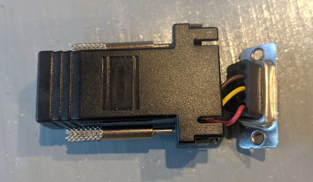
Section titled “Building the cable”Renogy used to include a USB-to-RJ12 cable with their charge controllers, but stopped after introducing their Bluetooth module. We need to build our own.
The three components: the USB serial dongle (for the correct protocol), the DB9-to-RJ12 adapter, and the RJ12 cable (with correct pin mapping for the Renogy controller).
The Renogy charge controller’s RJ12 pinout is: TX / RX / GND / GND / +12V / +12V. On the USB serial dongle: pin 2 is RXD, pin 3 is TXD, pin 5 is GND. Connect RJ12 TX → serial dongle RXD and RJ12 RX → serial dongle TXD, plus GND.
Step 1 — Identify the serial port
Section titled “Step 1 — Identify the serial port”With the cable connected between the Pi and charge controller, find the USB serial dongle’s device name:
pi@raspberrypi:~ $ ls /dev/*USB*/dev/ttyUSB0Step 2 — Install Solarshed
Section titled “Step 2 — Install Solarshed”Someone has already written a Python library called Solarshed that handles reading data from the Renogy controller:
https://github.com/corbinbs/solarshed
Install it with:
pip install solarshedStep 3 — Run the MQTT publisher script
Section titled “Step 3 — Run the MQTT publisher script”I wrote a script that reads the current solar power from the charge controller every second using Solarshed and publishes the data to the MQTT server on the Pi:
If your serial dongle is at a different address, change this line:
controller = RenogyRover('/dev/ttyUSB0', 1)Step 4 — Create a systemd service
Section titled “Step 4 — Create a systemd service”To keep the script always running, turn it into a systemd service:
sudo nano /lib/systemd/system/solar_mqqt.serviceAdd the following, updating the ExecStart path to match your script location:
[Unit]Description=Solar MQTTAfter=multi-user.target
[Service]Type=idleExecStart=/usr/bin/python3 /home/pi/python/solar/solar_mqtt.pyWorkingDirectory=/home/piUser=piRestart=on-failureRestartSec=5s
[Install]WantedBy=multi-user.target
Enable and start the service:
sudo systemctl daemon-reloadsudo systemctl enable solar_mqqt.serviceCheck that it’s running:
sudo systemctl status solar_mqtt.serviceStep 5 — Add the sensor to Home Assistant
Section titled “Step 5 — Add the sensor to Home Assistant”In Home Assistant, go to Configuration → Integrations and add the MQTT integration. Then add the following to your configuration.yaml:
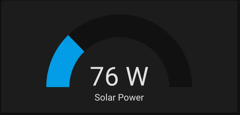
sensor: - platform: mqtt state_topic: "van/solar/power" name: 'Solar Power' unit_of_measurement: 'W' value_template: '{{ value_json.power }}'Restart Home Assistant and add the sensor to your dashboard: