Controlling the Lights
With Home Assistant installed we can now add a first interface: control of the lights. This involves some wiring, soldering, and circuit work, so a basic understanding of circuits is recommended.
What you’ll need
Section titled “What you’ll need”- Raspberry Pi Starter Kit — If you’re new to electronics, a starter kit comes with basic components, wires, a breadboard, and a GPIO extension board useful for prototyping.
- Soldering Iron — A basic kit will do.
- Multimeter — Always check for shorts before powering circuits. I upgraded to Fluke after a cheaper one failed.
- N-Channel MOSFETs — Used to switch the lights on and off.
- 12V LED Lights — The lights I use in my van.
The circuit
Section titled “The circuit”The Raspberry Pi GPIO pins operate at 3.3V and can’t drive 12V lights directly. Instead, we use the GPIO pins to switch an N-Channel MOSFET, which in turn switches the 12V supply to the lights:
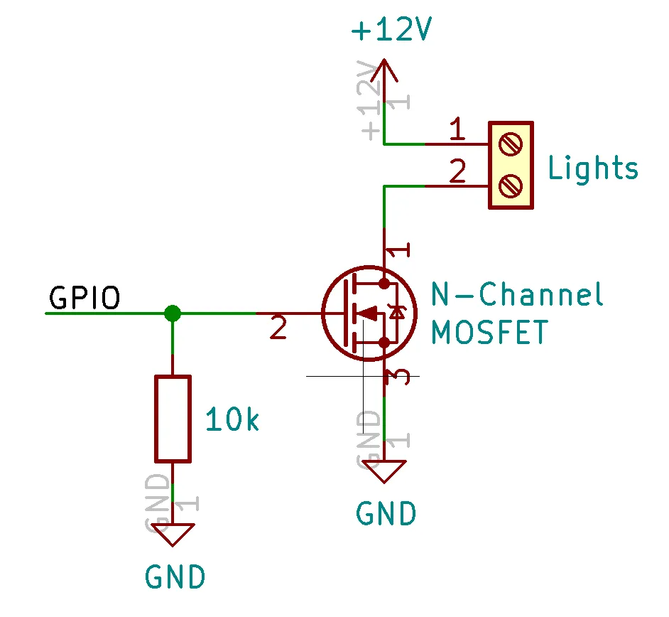
The GPIO pin drives the gate of the MOSFET (pin 2). When the gate voltage exceeds the threshold voltage, the MOSFET turns on and allows current to flow from the drain (pin 1) to the source (pin 3).
A 10kΩ resistor is added between gate and ground to keep the MOSFET off when the GPIO pin is unconfigured.
I assembled this by soldering wires directly to the MOSFETs and connecting the gate to a breadboard with the resistor and GPIO extension board:
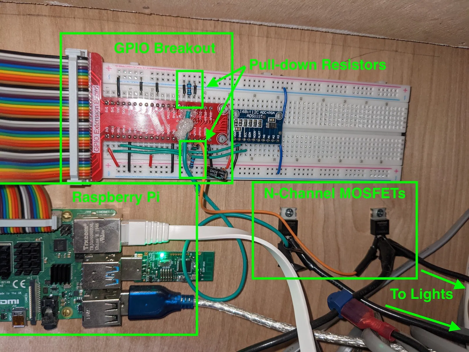
For GPIO pins, use GPIO 12, 13, 18, or 19 — these are the hardware PWM pins that allow dimming. I used 12 and 13, with the circuit replicated twice for two light zones.
Step 1 — Enable GPIO control
Section titled “Step 1 — Enable GPIO control”Install and enable pigpiod:
sudo apt-get install pigpiosudo systemctl enable pigpiodEnable remote GPIO via raspi-config:
sudo raspi-configChoose 3 - Interface Options → P8 - Remote GPIO → Yes. Exit and reboot.
Step 2 — Add lights to Home Assistant
Section titled “Step 2 — Add lights to Home Assistant”Navigate to your Home Assistant config directory and add the following to configuration.yaml:
light:- platform: rpi_gpio_pwm leds: - name: Bed Lights driver: gpio pins: [12] type: simple frequency: 50000 - name: Main Lights driver: gpio pins: [13] type: simple frequency: 50000This config sets up two light zones on GPIO 12 and 13. Adjust names and pin numbers to match your setup. For frequency, I experimented until I found a value that avoided visible flickering when dimmed — too low causes flickering, and some values cause a high-pitched ringing from the lights.
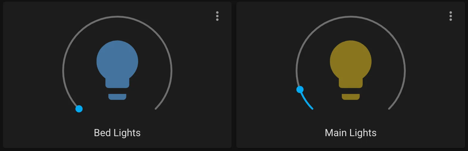
After restarting Home Assistant, you can add a light card to your dashboard:
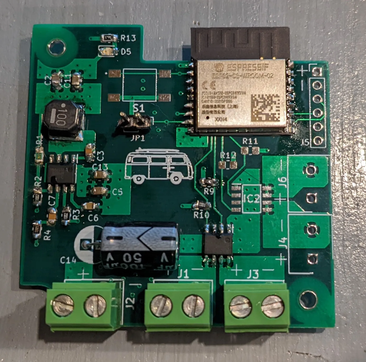
Update: Custom ESP32 PCB
Section titled “Update: Custom ESP32 PCB”I later designed a custom PCB using an ESP32 microcontroller to control the lights, cleaning up the wiring around the Pi. The same basic MOSFET circuit is used, but with PWM outputs from the ESP32 instead. KiCad files are here:
I originally planned to use ESPHome, but the PCB uses the ESP32-C3 which wasn’t supported by ESPHome yet. I ended up writing the firmware in C:
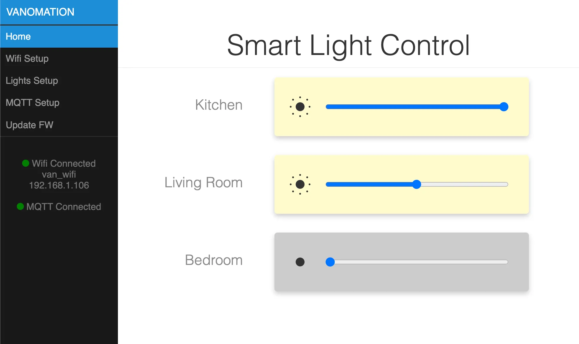
On first startup, the ESP32 starts in soft-AP mode and hosts a web server for configuration — WiFi network, light names, and MQTT server. With the MQTT integration in Home Assistant, the lights show up as devices automatically: